Newton's Laws of Motion
Learning Objectives
- Define force, mass, weight, and inertia in the context of classical mechanics and civil engineering.
- State and explain Newton's Three Laws of Motion and their implications on structural equilibrium.
- Draw accurate Free Body Diagrams (FBDs) for rigid bodies in various structural and mechanical scenarios.
- Apply Newton's Second Law to solve dynamics problems involving constant acceleration, friction, inclines, and pulleys.
- Analyze circular motion using centripetal force concepts relevant to transportation and structural stability.
The Concept of Force
The Concept of Force Concepts
A force is intuitively defined as a push or a pull on an object resulting from its interaction with another object. Forces are vector quantities, meaning they have both magnitude and direction.
Net Force ()
The vector sum of all individual forces acting simultaneously on an object. The behavior of the object depends solely on this net force, not the individual forces themselves.
Net Force
Calculates the net force acting on an object as the vector sum of all individual forces.
Variables
| Symbol | Description | Unit |
|---|---|---|
| Net force | N | |
| Individual forces | N |
Interactive Simulation: Vector Addition
Use this vector model to combine force components and see how the net force direction changes as each applied force changes.
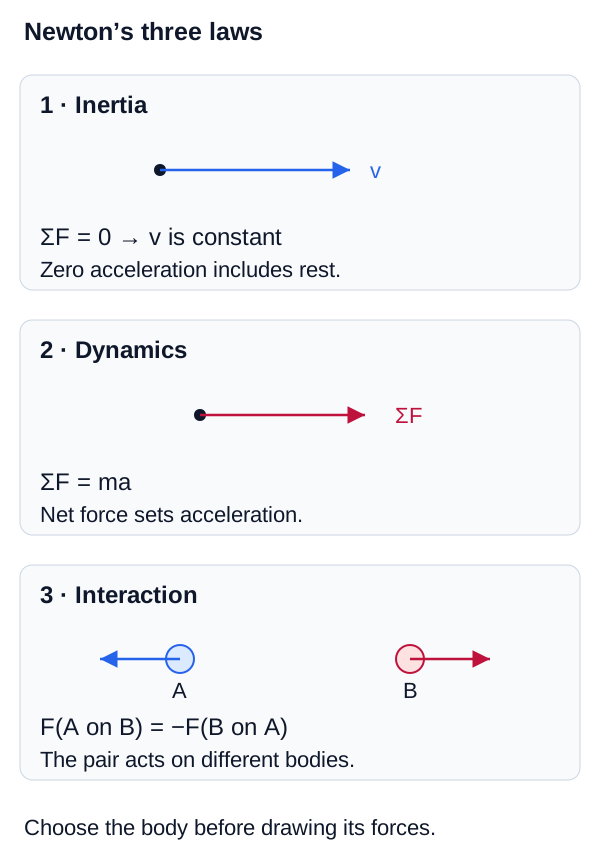
Three-law map
Newton's three laws
Use the law that matches the physical question rather than treating the three laws as interchangeable formulas.
Newton's First Law: Inertia
Newton's First Law: Inertia Concepts
Newton's First Law states: "An object at rest stays at rest, and an object in motion stays in motion with the same speed and in the same direction, unless acted upon by an unbalanced force."
This law defines a fundamental property of matter called inertia.
Inertia
The natural tendency of an object to resist changes in its state of motion. Mass is a quantitative measure of an object's inertia. A massive object is much harder to accelerate or decelerate than a light one.
Translational Equilibrium
The First Law implies that if the net force on an object is zero (), the object's acceleration is zero (). This means its velocity is constant. For a body in static equilibrium, both translational and rotational equilibrium must be satisfied: the net force and the net moment are zero.
Newton's Second Law:
Newton's Second Law: Concepts
Newton's Second Law quantifies the relationship between force, mass, and acceleration: "The acceleration of an object as produced by a net force is directly proportional to the magnitude of the net force, in the same direction as the net force, and inversely proportional to the mass of the object."
This is famously summarized by the equation:
Newton's Second Law
Quantifies the relationship between force, mass, and acceleration.
Variables
| Symbol | Description | Unit |
|---|---|---|
| Net force vector | N | |
| Mass of the object | kg | |
| Resulting acceleration vector |
Interactive Simulation: Newton's Second Law
Adjust the mass and applied net force below to see how Newton's Second Law converts force imbalance into acceleration.
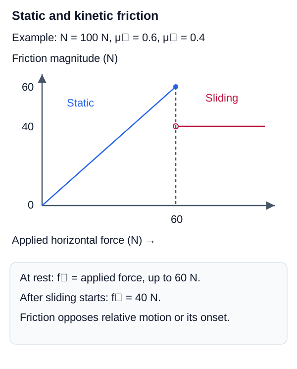
The kinetic coefficient control is constrained to μk ≤ μs. Before motion begins, static friction exactly opposes the applied force up to μsN; kinetic friction is used only after the applied force exceeds that limit.
Common Misconception
The equation tells us that net force causes acceleration. It is incorrect to think of "" as a force itself. It is the result of the forces. If you are drawing forces on an object, never draw "" as an arrow.
Newton's Third Law: Action and Reaction
Newton's Third Law: Action and Reaction Concepts
Newton's Third Law states: "For every action, there is an equal and opposite reaction."
More precisely: If object A exerts a force on object B, then object B simultaneously exerts a force on object A. These forces are equal in magnitude but opposite in direction.
Newton's Third Law
Describes the action-reaction force pair between two interacting objects.
Variables
| Symbol | Description | Unit |
|---|---|---|
| Force exerted by object A on object B | N | |
| Force exerted by object B on object A | N |
Action-Reaction Pairs
Action and reaction forces always act on different objects. They never cancel each other out when analyzing the motion of a single object because they are not applied to the same object.
Interaction-pair versus FBD visual
Third-law interaction pairs and free-body diagrams
Equal and opposite interaction forces do not cancel on one free-body diagram because they act on different systems.

Mass vs. Weight
Mass vs. Weight Concepts
In engineering physics, mass and weight are distinctly different concepts.
Mass ()
A fundamental scalar property of an object representing its inertia (resistance to acceleration) and the amount of matter it contains. Mass is intrinsic to the object and remains constant regardless of its location in the universe (in kg).
Weight ()
The force exerted on an object by gravity. Weight is a vector quantity pointing downwards towards the center of the earth. It depends on the local acceleration due to gravity (). Because weight is a force, its SI unit is the Newton (N).
Weight
Calculates the gravitational force acting on an object of given mass.
Variables
| Symbol | Description | Unit |
|---|---|---|
| Weight (gravitational force) | N | |
| Mass of the object | kg | |
| Acceleration due to gravity |
Common Types of Forces
Normal Force ( or )
A contact force exerted by a surface on an object resting against it. It is always perpendicular (normal) to the surface. It prevents the object from passing through the surface.
Tension ()
A pulling force exerted by a taut string, rope, or cable. It acts away from the object and parallel to the rope. Ideal ropes are massless and do not stretch, transmitting force uniformly.
Friction ()
A contact force that resists relative motion between surfaces. It acts parallel to the surfaces in contact.
- Static Friction (): Opposes impending relative sliding at a contact and self-adjusts as needed, subject to . A body can still be moving while a contact remains in static friction, as in ideal rolling without slipping.
- Kinetic Friction (): Opposes relative sliding at the contact. In the elementary Coulomb model, its magnitude is .
Drag Force ( or )
A fluid friction force (air resistance) that opposes the motion of an object through a fluid. At high speeds, it is typically proportional to the square of the velocity ().
Applied Force ()
A general term for any external push or pull actively applied by a person or machine.
Common Types of Forces Concepts
When applying Newton's Laws to engineering problems, several specific forces frequently appear. Understanding these forces is essential for constructing accurate Free Body Diagrams.
Static and kinetic friction visual
Static and kinetic friction regimes
Before sliding, friction matches the required opposing force up to its maximum. After sliding, kinetic friction is modeled as mu-k times the normal force.
Apparent Weight
Apparent Weight Concepts
Your "weight" as you feel it (or as a scale measures it) is actually the Normal force exerted on you by the floor or scale, not the force of gravity itself. If you are in an elevator accelerating upwards, the normal force must be greater than gravity to produce the upward net force, so you feel heavier (your apparent weight is greater than your actual weight). In free fall, the normal force is zero, leading to the sensation of "weightlessness."
Free Body Diagrams (FBDs)
Free Body Diagrams (FBDs) Concepts
The most important step in solving any dynamics or statics problem is drawing a Free Body Diagram (FBD).
Free Body Diagram
A simplified sketch showing an object isolated from its surroundings, with all external forces acting on that object drawn as vectors pointing outwards from its center of mass.
How to draw an FBD
-
- Define the system: Clearly identify the specific object you are analyzing.
-
- Represent the object as a point particle (for translational motion).
-
- Identify all points of contact and fields (gravity).
-
- Draw and label all external force vectors acting on the object (Weight, Normal, Tension, Friction, Applied). Do not include internal forces or forces the object exerts on other things.
-
- Choose a convenient coordinate system (e.g., align the x-axis with the direction of acceleration).
Applying Newton's Second Law to FBDs
Once the FBD is drawn, you apply Newton's Second Law in component form:
Dynamics of Circular Motion
Dynamics of Circular Motion Concepts
When an object undergoes uniform circular motion, it experiences centripetal acceleration () directed towards the center of the circle. By Newton's Second Law, there must be a net force producing this acceleration. This net force is commonly called the centripetal force.
Centripetal Force
Calculates the net radial force required to maintain uniform circular motion.
Variables
| Symbol | Description | Unit |
|---|---|---|
| Centripetal (net radial) force | N | |
| Mass of the object | kg | |
| Centripetal acceleration | ||
| Tangential velocity | ||
| Radius of the circular path | m |
Centripetal Force Concept
Centripetal force is not a new, separate type of force (like gravity or tension). It is simply the net radial force resulting from actual physical forces (like the tension in a string swinging a mass, or static friction keeping a car turning on a curved road).
Applications of Newton's Laws
Friction, Inclines, and Pulleys
Applying Newton's Laws to practical engineering scenarios often involves interconnected systems, inclined planes, and friction.
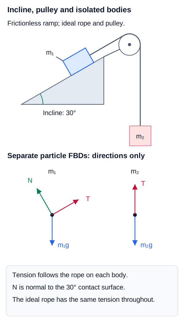
- Inclined Planes: When an object rests on an incline of angle , gravity is no longer purely perpendicular to the surface. The weight vector () must be resolved into components: (parallel to the incline, driving motion) and (perpendicular to the incline, opposing the Normal force).
- Pulleys (Atwood Machines): Ideal pulleys change the direction of tension without changing its magnitude. When analyzing connected masses, it is often useful to treat the entire string as a single 1D axis of motion, or to draw separate Free Body Diagrams for each mass and link them via the shared tension and acceleration .
Incline and pulley FBD visual
Incline and pulley free-body diagrams
The diagram separates the two bodies while preserving the shared ideal-string tension and acceleration constraint.
- First Law: Objects have inertia; without a net force, velocity is constant. .
- Second Law: Net force causes acceleration inversely proportional to mass. .
- Third Law: Forces always exist in pairs acting on different objects. .
- Mass is intrinsic (kg); Weight is the force of gravity (, N).
- Free Body Diagrams (FBDs) are essential for isolating an object and analyzing the external forces before applying equations.