Optics and Light
Learning Objectives
- Understand the dual nature of light and its properties as an electromagnetic wave.
- Apply the principles of geometric optics, including reflection and refraction, to analyze light ray behavior.
- Calculate image formation using mirrors and thin lenses.
- Explain physical optics phenomena such as interference, diffraction, and polarization.
The Nature of Light
The Nature of Light Concepts
Historically, there was a great debate over whether light was a stream of particles or a wave. We now know that light exhibits properties of both, a concept known as wave-particle duality.
In optics, we primarily treat light as an electromagnetic wave.
Electromagnetic Wave
A self-propagating transverse wave consisting of oscillating electric and magnetic fields that are perpendicular to each other and to the direction of propagation. Light waves do not require a medium to travel.
The Nature of Light Concepts
The speed of light in a vacuum () is a universal constant:
Electromagnetic Spectrum and Wavelength
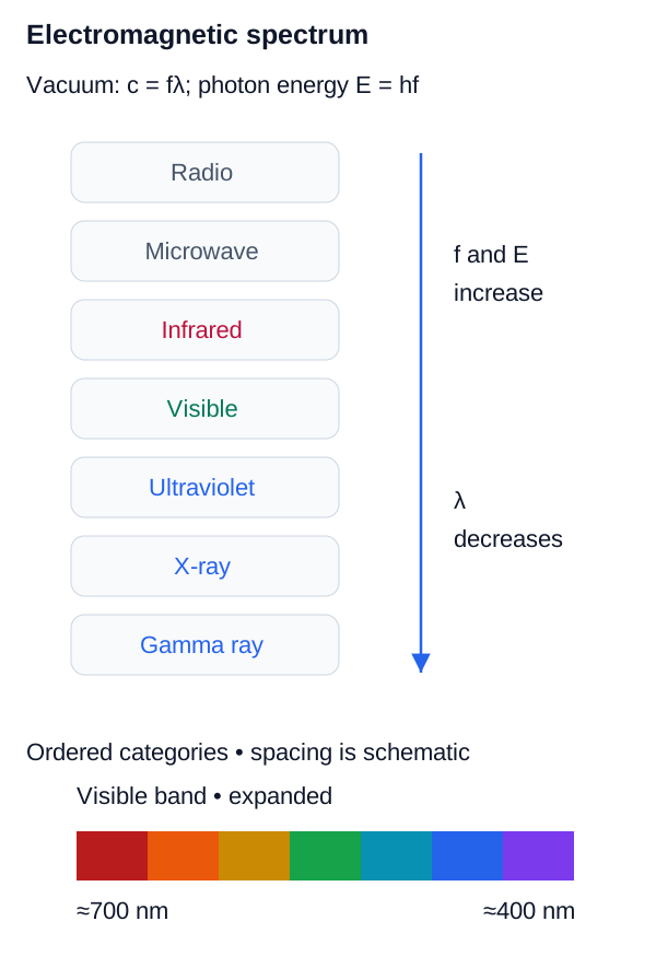
The visible spectrum is a very narrow band of electromagnetic radiation with wavelengths ranging from approximately 400 nm (violet) to 700 nm (red). Other regions of the spectrum include radio waves, microwaves, infrared, ultraviolet, X-rays, and gamma rays. All travel at the speed of light in a vacuum.
Wave Equation for Light
Relates the speed of light to its wavelength and frequency.
Variables
| Symbol | Description | Unit |
|---|---|---|
| Speed of light | m/s | |
| Frequency | Hz | |
| Wavelength | m |
Applications of the Electromagnetic Spectrum
- Radio and Microwaves: Used for communication, radar, and Wi-Fi networks.
- Infrared: Used in thermal imaging, night vision, and optical fiber communications.
- Ultraviolet: Used for sterilization and water purification in civil infrastructure.
- X-rays: Employed in non-destructive testing of welds and concrete structures.
Electromagnetic Spectrum Relationship
All electromagnetic waves share c=fλ in vacuum; increasing frequency corresponds to decreasing wavelength, with visible light occupying only a small portion of the spectrum.
Geometric Optics
Geometric Optics Concepts
When light interacts with objects much larger than its wavelength (like mirrors, lenses, and prisms), we can approximate its behavior using rays—straight lines representing the direction of energy flow. This is the domain of Geometric Optics.
Reflection and Refraction
Reflection and Refraction Concepts
When a light ray strikes a boundary between two different transparent media, some of the light is reflected back into the first medium, and some is transmitted (refracted) into the second medium.
Index of Refraction ()
A dimensionless ratio relating the speed of light in vacuum to the phase velocity of light in a medium at a specified frequency.
Index of Refraction
Relates refractive index to light speed in vacuum and phase velocity in a medium.
Variables
| Symbol | Description | Unit |
|---|---|---|
| Refractive index | dimensionless | |
| Speed of light in vacuum | m/s | |
| Phase velocity in the medium | m/s |
Typical Refractive Indices
Vacuum has exactly. Air near standard conditions is close to , while common optical glasses are typically around in the visible range; refractive index varies with wavelength and material composition.
The Laws of Reflection and Refraction
When a light ray strikes a boundary, it follows two fundamental laws regarding its angle relative to the surface normal.
The Law of Reflection
States that the angle of incidence equals the angle of reflection.
Variables
| Symbol | Description | Unit |
|---|---|---|
| Angle of incidence | ||
| Angle of reflection |
Snell's Law (Law of Refraction)
Relates the indices of refraction and the angles of incidence and refraction for a light ray crossing a boundary.
Variables
| Symbol | Description | Unit |
|---|---|---|
| Index of refraction of the first medium | dimensionless | |
| Angle of incidence | ||
| Index of refraction of the second medium | dimensionless | |
| Angle of refraction |
Total Internal Reflection (TIR)
When light travels from a medium with a higher index of refraction to one with a lower index (), the refracted ray bends away from the normal. If the incident angle is greater than the critical angle, all light is reflected back into the first medium. This is the principle behind fiber optics.
Critical Angle
The minimum angle of incidence at which total internal reflection occurs.
Variables
| Symbol | Description | Unit |
|---|---|---|
| Critical angle | ||
| Index of refraction of the less dense medium | dimensionless | |
| Index of refraction of the denser medium | dimensionless |
Interactive Simulation: Ray Optics
Use this ray-optics model to connect incidence, refraction, and reflection behavior at an interface.
Mirrors and Lenses
Mirrors and Lenses Concepts
We use curved mirrors (spherical) and thin lenses to form images by reflection or refraction. Images can be real (light rays actually converge at the image point) or virtual (light rays appear to diverge from the image point).
- Concave Mirrors / Convex Lenses: Converging elements. They can form real or virtual images depending on object distance.
- Convex Mirrors / Concave Lenses: Diverging elements. For a real object in the usual paraxial arrangement, they form upright, reduced, virtual images.
For thin lenses and spherical mirrors, the relationship between object distance (), image distance (), and focal length () is given by:
The Mirror/Thin Lens Equation
Relates the object distance, image distance, and focal length for spherical mirrors and thin lenses.
Variables
| Symbol | Description | Unit |
|---|---|---|
| Object distance | m | |
| Image distance | m | |
| Focal length | m |
Lateral Magnification
The ratio of image height to object height, or negative image distance to object distance.
Variables
| Symbol | Description | Unit |
|---|---|---|
| Lateral magnification | dimensionless | |
| Image height | m | |
| Object height | m | |
| Image distance | m | |
| Object distance | m |
Sign Conventions for Mirrors and Lenses
- for a real object in front of the lens/mirror.
- for a real image (formed by actual converging rays).
- for a virtual image.
- for converging lenses/mirrors.
- for diverging lenses/mirrors.
- means the image is upright; means it is inverted.
Interactive Simulation: Thin Lenses
Use this thin-lens model to see image distance, orientation, and magnification change with object position.
Physical (Wave) Optics
Physical (Wave) Optics Concepts
When light interacts with objects whose dimensions are comparable to its wavelength (like tiny slits or the spacing between atoms in a crystal), geometric ray optics fails. We must treat light as a wave to explain interference and diffraction.
Huygens' Principle
Huygens' Principle Concepts
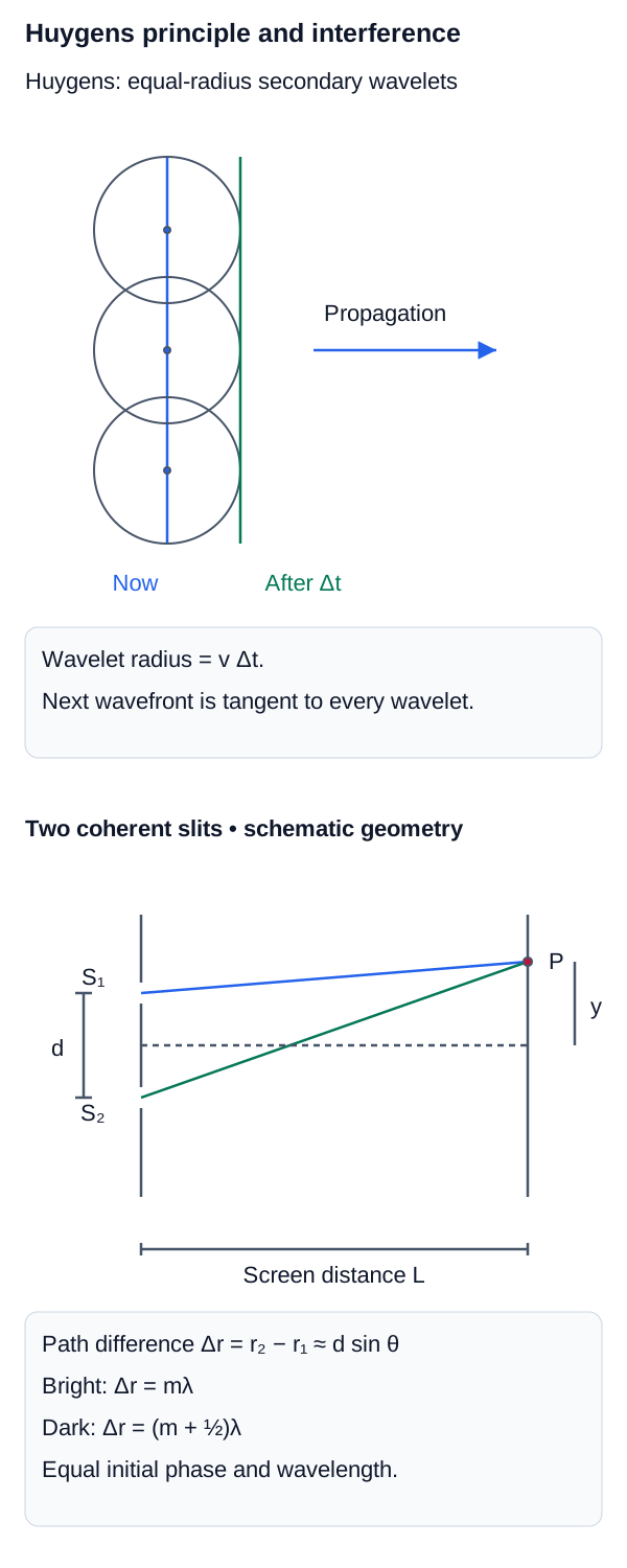
A geometrical method for predicting the future position of a wavefront. Every point on a wavefront is treated as a source of secondary wavelets. The later wavefront is constructed as the forward envelope tangent to those wavelets; a full wave treatment is required to account for amplitudes and the suppression of a backward wave.
Huygens Construction and Double-Slit Interference
The upper panel constructs the next wavefront as the envelope of secondary wavelets; the lower panel links two coherent slits to path difference and interference fringes.
Interference
Interference Concepts
As discussed in the waves chapter, when two light waves meet, they superimpose according to their relative phase.
In Young's Double-Slit Experiment, two narrow slits illuminated by the same coherent source act as secondary sources with a stable relative phase. Their waves overlap at a distant screen and form alternating bright and dark fringes.
- Constructive Interference (Bright Fringes / Maxima): Occurs when the path length difference () from the two slits to the screen is an integer multiple of the wavelength (). This means the waves arrive "in phase" (crest to crest).
- Destructive Interference (Dark Fringes / Minima): Occurs when the path difference is a half-integer multiple of the wavelength (). The waves arrive "out of phase" (crest to trough) and cancel each other out.
Young Double-Slit Interference
Path-difference conditions and the small-angle fringe-position relation for two narrow coherent slits.
For a distant screen with ,
Variables
| Symbol | Description | Unit |
|---|---|---|
| Center-to-center slit separation | m | |
| Observation angle from the central axis | ||
| Interference order | integer | |
| Wavelength in the propagation medium | m | |
| Slit-to-screen distance | m | |
| Small-angle position of the m-th bright fringe | m |
Diffraction
Diffraction Concepts
Diffraction is the bending of light waves around obstacles or through narrow openings. It is a direct consequence of Huygens' principle. If light were purely particles, an opening would cast a sharp shadow. Instead, light "leaks" into the shadow region.
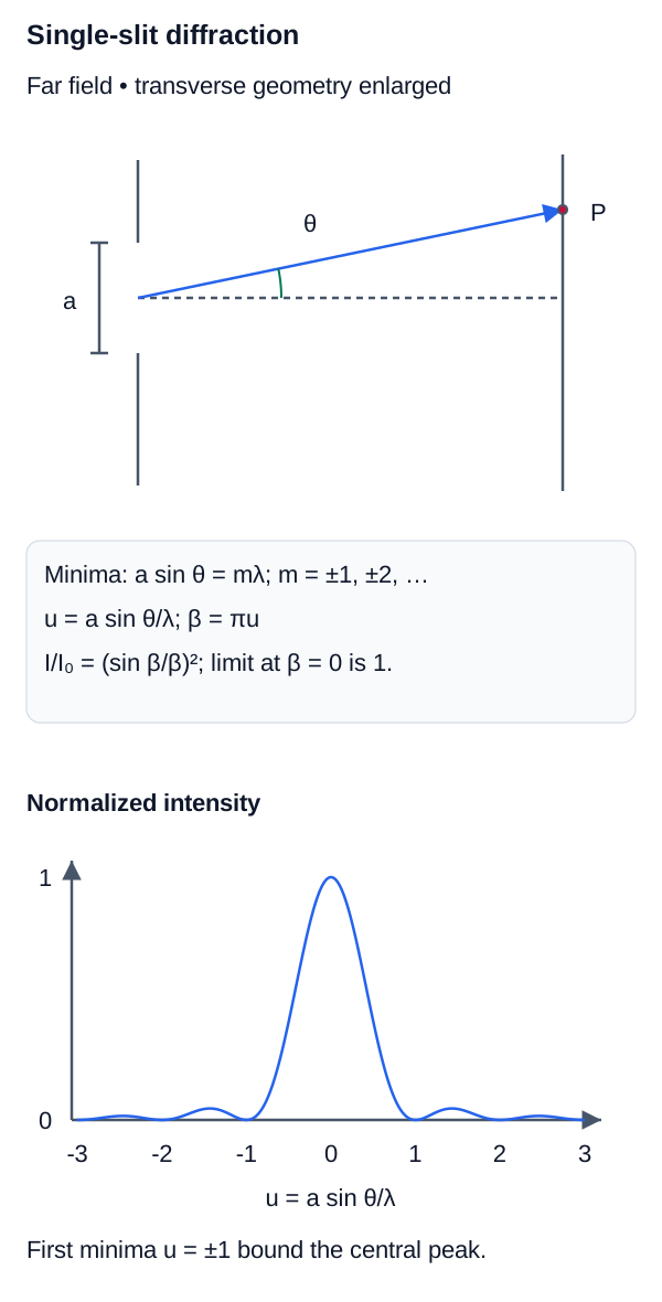
In Single-Slit Diffraction, a single narrow opening creates a central bright maximum flanked by alternating, less intense dark and bright fringes. This occurs because wavelets from different parts of the same slit interfere with each other.
Single-Slit Diffraction Minima
Angular locations of dark minima for Fraunhofer diffraction from a slit of width a.
For small angles on a screen a distance away, the central-maximum width is approximately
Variables
| Symbol | Description | Unit |
|---|---|---|
| Slit width | m | |
| Angle of a diffraction minimum from the central axis | ||
| Nonzero diffraction-minimum order | integer | |
| Wavelength in the propagation medium | m | |
| Slit-to-screen distance | m | |
| Approximate width of the central maximum | m |
Single-Slit Diffraction Geometry
A finite slit produces angular spreading; minima occur when a sinθ=mλ for nonzero integer m, and the central maximum is wider than the adjacent maxima.
Polarization
Polarization Concepts
Because light is a transverse wave, its electric field can oscillate in any direction perpendicular to the direction of propagation. Unpolarized light (like sunlight) has electric fields oscillating in all possible random directions.
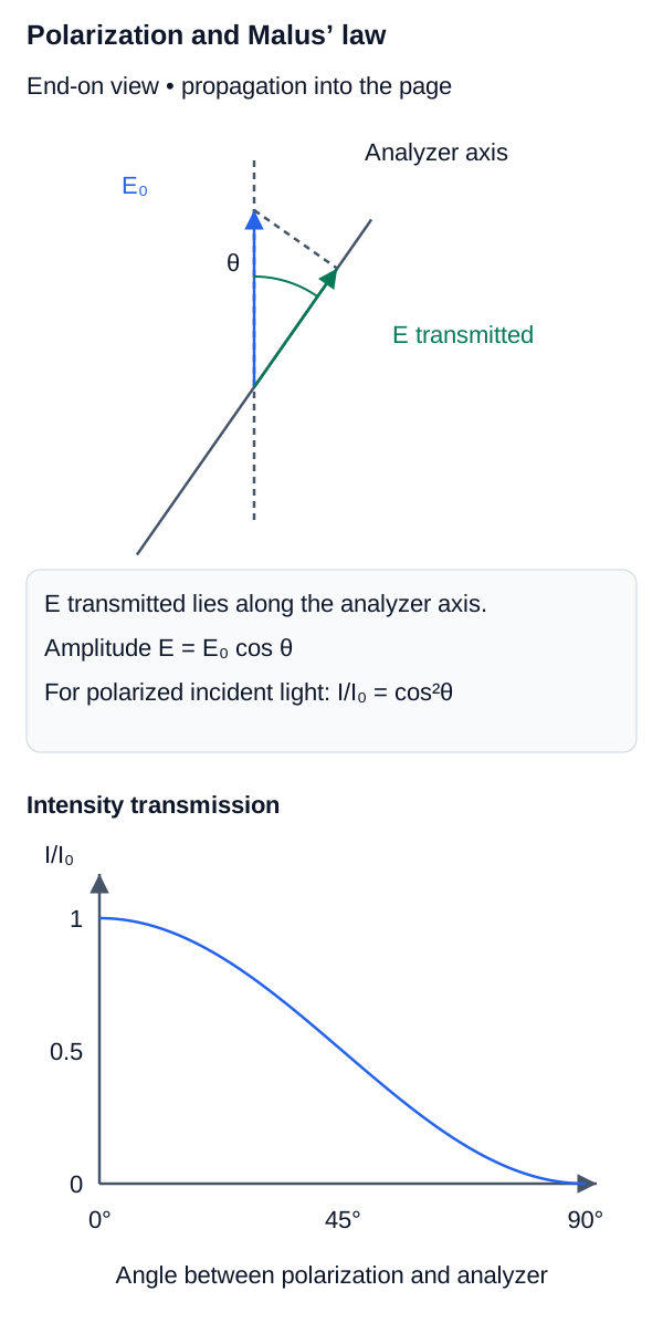
Polarization describes the orientation behavior of a transverse wave's electric field. Linear polarization confines the electric-field direction to a fixed line in the transverse plane; circular and elliptical polarization are also possible. An ideal linear polarizer transmits the field component along its transmission axis, and unpolarized incident light emerges with average intensity .
Malus' Law
Intensity transmitted by an ideal analyzer for linearly polarized incident light.
Variables
| Symbol | Description | Unit |
|---|---|---|
| Transmitted intensity | ||
| Intensity incident on the analyzer | ||
| Angle between polarization direction and analyzer transmission axis | rad or deg |
Polarization and Malus' Law
The analyzer transmits the electric-field component along its axis, giving I=I0 cos²θ for linearly polarized incident light.
Polarization Mechanisms
Methods of Polarization
Beyond polarizing filters, light can become polarized naturally through several mechanisms:
- Polarization by Reflection: When light reflects from a dielectric interface at Brewster's angle, the reflected component is ideally linearly polarized perpendicular to the plane of incidence (s-polarized). At Brewster incidence, the reflected and refracted rays are perpendicular.
- Polarization by Scattering: Sunlight scattered by molecules in the Earth's atmosphere becomes partially polarized. This is why polarizing sunglasses are effective at reducing sky glare.
- Light acts as an electromagnetic wave but interacts with matter in quantized units called photons. The speed of light .
- The Index of Refraction () describes how light slows down in a medium.
- Geometric Optics uses rays. The Law of Reflection () and Snell's Law of Refraction () govern how rays bend at interfaces.
- Total Internal Reflection occurs only for when the incidence angle exceeds the critical angle, .
- The Mirror/Thin Lens Equation () predicts the location () and magnification () of images.
- Physical Optics treats light as a wave to explain phenomena like Interference (Young's double slit) and Diffraction (bending around obstacles), where path length differences determine constructive or destructive interference.
References
- OpenStax University Physics Volume 3 — Electromagnetic Waves
- OpenStax University Physics Volume 3 — Geometric Optics and Image Formation
- OpenStax University Physics Volume 3 — Interference
- OpenStax University Physics Volume 3 — Diffraction
- OpenStax University Physics Volume 3 — Polarization
- BIPM — SI Brochure