Simple Strain and Deformation
Learning Objectives
- Distinguish deformation from normal strain and compute each consistently.
- Relate stress and strain in the linear-elastic range using Hooke's law.
- Interpret the essential regions of an engineering stress-strain curve.
- Compute axial deformation for prismatic and segmented members.
- Apply Poisson's ratio, shear modulus, and bulk modulus relationships within their elastic assumptions.
Normal Strain
Normal strain is the change in length divided by the original gauge length. It is dimensionless.
Normal Strain
Average axial strain over an original length.
Modulus of Elasticity
The modulus of elasticity is the slope of the linear portion of the normal stress-strain curve.
Hooke's Law
Linear-elastic normal stress-strain relation.
Stress-Strain Behavior
An engineering stress-strain curve distinguishes elastic behavior, yielding, strain hardening, ultimate strength, necking, and fracture for ductile materials. Hooke's law applies only where the response is approximately linear and elastic. Beyond that range, deformation is not fully recoverable and a linear modulus alone cannot describe the material response.
Measuring Axial Strain
The specimen grips define the loading axis, while the extensometer tracks change in the central gauge length; the adjacent simulation and equations provide the stress-strain interpretation.
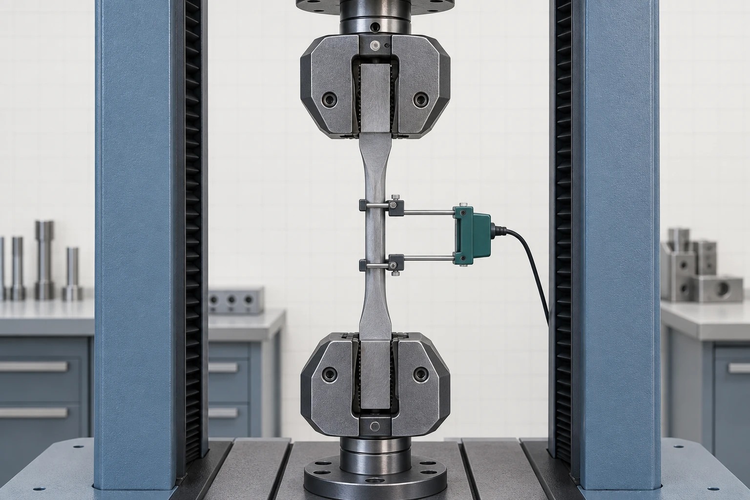
Reading the Test Setup
The central gauge section is the physical length whose change is used to compute axial strain, while the grips transfer the applied axial force. This generated laboratory context does not provide a measured curve, material property, or test result; use the existing stress-strain visualizer for response regions and the strain formulas for calculation.
Material-Behavior Visualization
Compare explicitly idealized ductile and brittle stress-strain responses. The curves are qualitative teaching models rather than material specification data, so use them to understand response regions—not to obtain design strengths.
Controls
Value from the selected schematic teaching curve.
Illustrates elastic response, yielding, strain hardening, and engineering-stress decline after the peak.
Material-specific strengths, strains, unloading, cyclic behavior, and multiaxial effects are outside this teaching surface.
Interactive Exploration
Use the deformation visualizer to connect load, stress, strain, and axial elongation. Compare the moving operating point with the stated yield boundary and identify where the linear-elastic model stops reporting deformation.
Controls
Elastic stress-strain response
Area fixed at 500 mm².
Hooke's law is used.
E = 200 GPa.
Original length = 2000 mm.
Axial Deformation
Axial deformation is the total change in member length caused by axial force, material stiffness, and geometry.
Axial Deformation of a Prismatic Member
Elastic deformation for constant axial force, area, and modulus.
Segmented and Stepped Members
For members with multiple segments, compute the signed deformation of each segment and sum them: . Tension contributes elongation; compression contributes shortening under the chosen sign convention.
Stepped-Bar Deformation Context
The serial segments provide physical context for summing signed segment deformations; use the adjacent elastic formula for exact values.
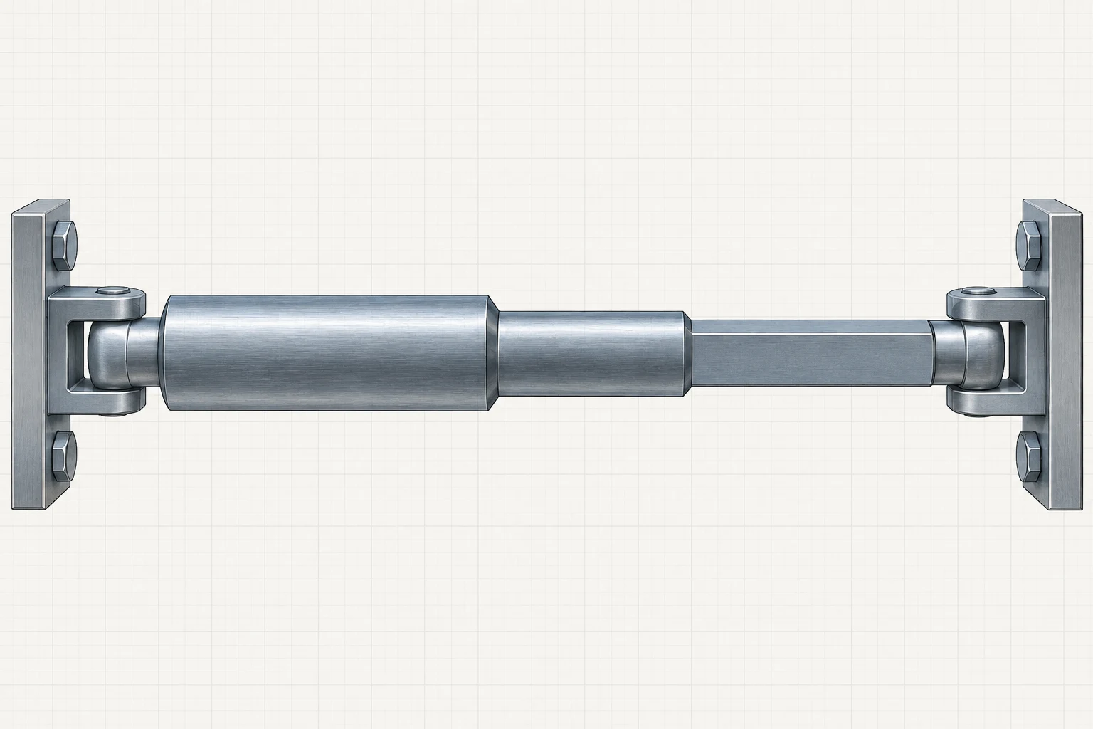
Reading the Stepped Member
Each shoulder belongs to the same connected load path, so total axial deformation is built from the signed contribution of each segment. The image is not to scale and does not provide segment dimensions or elongation.
Statically Indeterminate Axial Members
When reactions cannot be found from equilibrium alone, add deformation compatibility. Typical compatibility statements require connected points to have the same displacement or a constrained gap to close by a prescribed amount. Combine equilibrium, constitutive behavior, and compatibility before solving the unknown forces.
Compatible Parallel Members
The shared plates make the common end displacement visible; equilibrium and compatibility determine the individual member forces.
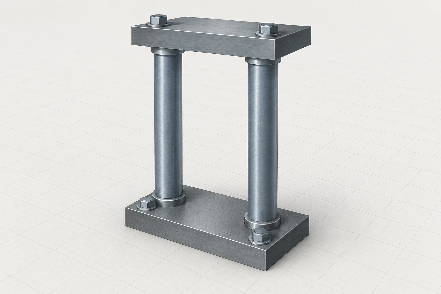
Reading the Common End Plates
Because both members meet the same rigid end plates, their connected ends share the plate displacement in the idealized model. The raster does not determine reaction values, stiffness ratios, or a unique load split.
Poisson's Ratio
Poisson's ratio is the negative ratio of lateral strain to longitudinal strain in uniaxial loading.
Poisson's Ratio
Relationship between lateral and longitudinal strain under uniaxial elastic loading.
Axial Elongation and Lateral Contraction
The lower specimen is qualitatively longer with a slightly narrower gauge section; use the Poisson formula for the signed strain relationship.
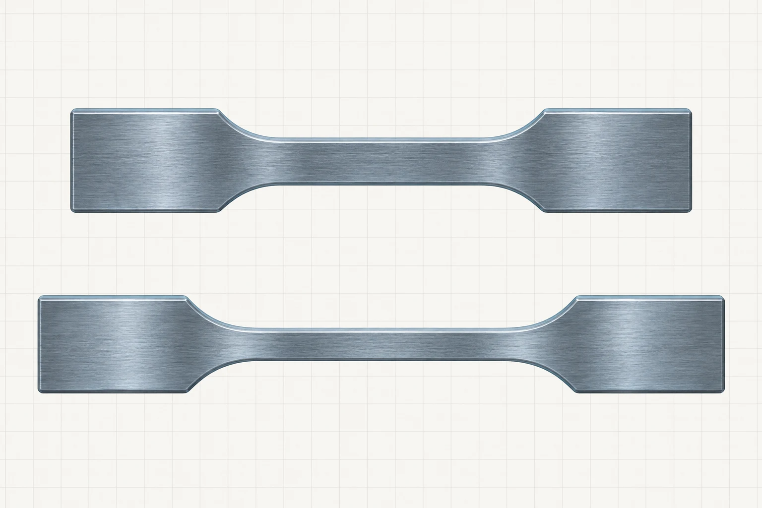
Reading the Specimen States
The paired shapes illustrate longitudinal extension together with lateral contraction under uniaxial tension. The change is qualitative rather than measured; the raster gives no strain magnitude, material property, or Poisson ratio.
Elastic Modulus Relationship
Relationship among Young's modulus, shear modulus, and Poisson's ratio for isotropic linear-elastic materials.
Bulk Modulus Relationship
Relationship among bulk modulus, Young's modulus, and Poisson's ratio for isotropic linear-elastic materials.
Elastic-Constant Shape Changes
The separated block states distinguish axial stretch, angular shear distortion, and volume-changing compression; use the adjacent formulas for exact elastic relationships.
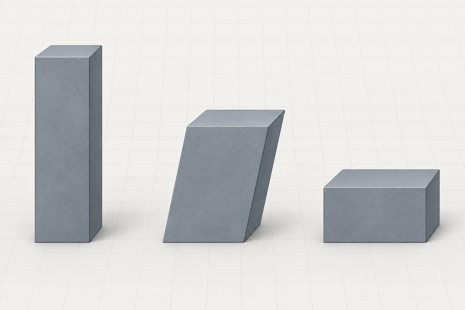
Reading the Material States
The three blocks are qualitative shape cues: axial strain changes length, shear changes angles, and volumetric strain changes size. The shapes are not to scale and do not show axes, tensors, values, or a material-specific response.
Material-Model Limits
The elastic-constant relationships above assume a homogeneous, isotropic, linear-elastic material. Do not apply them unchanged to strongly anisotropic materials, nonlinear response, cracked composites, or other systems outside those assumptions.
- Strain measures deformation relative to original length; deformation has units of length.
- Hooke's law is a linear-elastic relation, not a universal stress-strain law.
- Axial deformation depends on force, length, area, and modulus.
- Indeterminate axial systems require compatibility in addition to equilibrium.
- Poisson's ratio links longitudinal and lateral strain, while , , and are related for isotropic linear-elastic materials.