Thin-Walled Pressure Vessels
Learning Objectives
- Check whether the thin-wall approximation is appropriate for a vessel.
- Derive and apply hoop and longitudinal membrane stresses in cylindrical vessels.
- Apply the membrane-stress relation for spherical vessels.
- Explain why cylinder hoop stress governs over longitudinal stress for equal geometry and pressure.
- Account conceptually for joint efficiency without confusing it with wall-thickness geometry.
Thin-Walled Pressure Vessel
A pressure vessel is treated as thin-walled when the wall thickness is small enough relative to radius that membrane stress can be approximated as uniform through the thickness. A common introductory criterion is .
Thin-Wall Applicability
When , through-thickness stress variation is no longer negligible and thin-wall membrane equations are not appropriate. Use a thick-cylinder formulation suitable for the problem instead.
Formed Thin Shell in Context
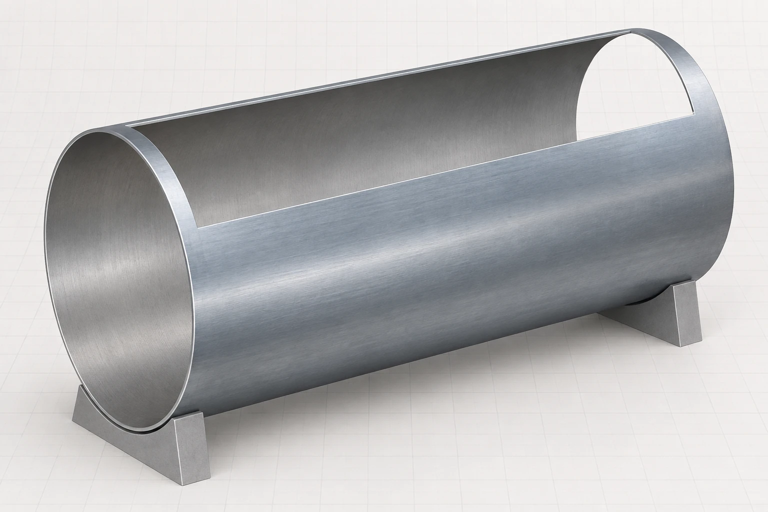
The formed shell shows the physical curved wall that is idealized as a membrane in the following equations; it carries no thickness or manufacturing claim.
From Formed Shell to Membrane Model
Observe the continuous curved wall and exposed interior surface before treating the vessel as a thin membrane. The raster is a qualitative physical-context aid: it supplies no thickness dimension, fabrication sequence, or design conclusion.
Cylinder Hoop Stress
Tangential membrane stress in a thin cylindrical pressure vessel.
Cylinder Longitudinal Stress
Axial membrane stress in a closed-end thin cylindrical pressure vessel.
Cylinder Free-Body Interpretation
Hoop stress resists the tendency of the cylinder to split along a longitudinal plane. Longitudinal stress resists the pressure force on the closed end caps. For the same , , and , the hoop stress is twice the longitudinal stress, so hoop stress usually controls a simple membrane-stress thickness check.
Closed End-Cap Junction
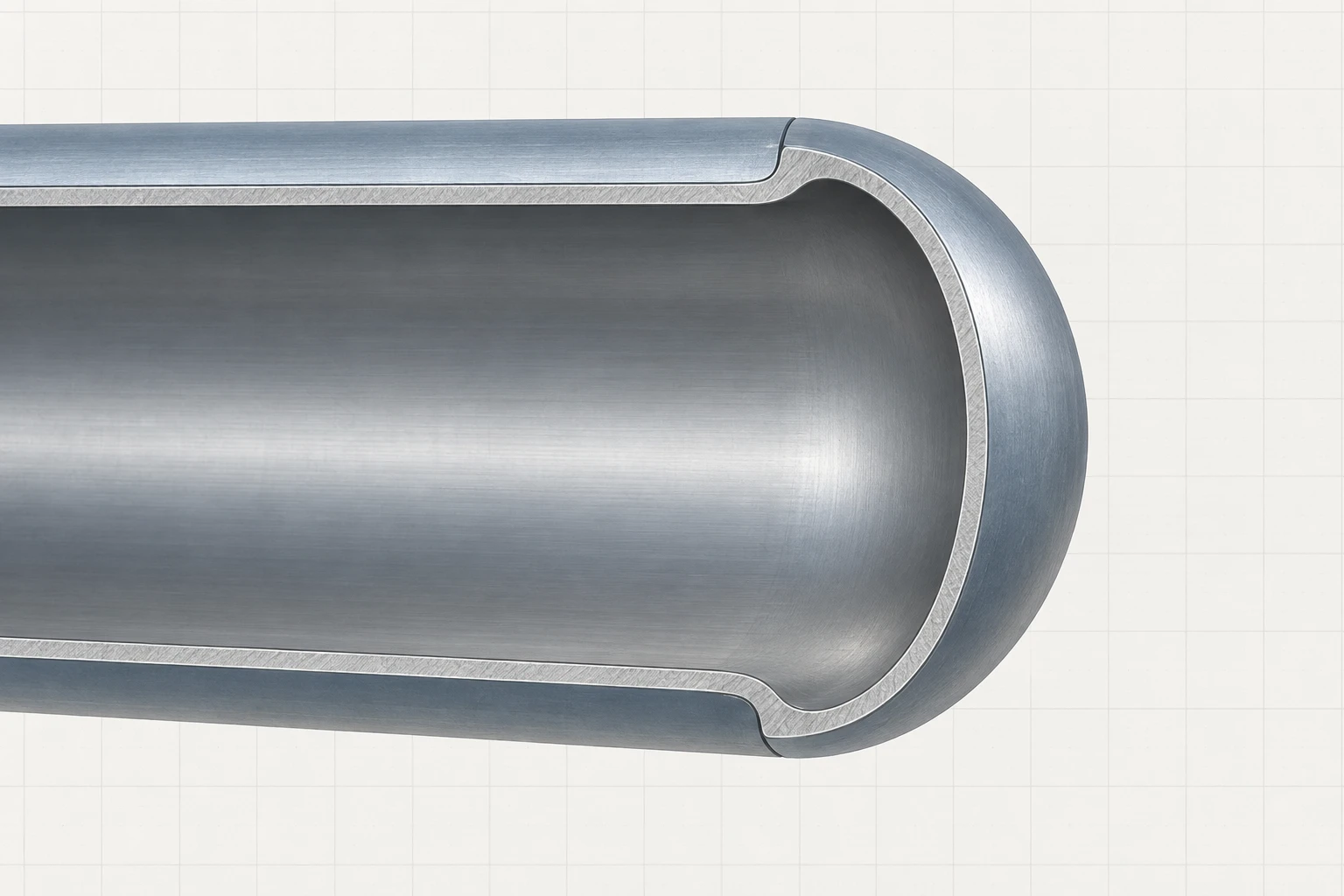
The sectional close-up shows the cylindrical shell flowing into a continuous rounded end cap, giving physical context for the closed-end load path behind longitudinal stress.
Reading the End-Cap Closure
Treat the cap-to-shell junction as the continuous boundary that closes the vessel. The raster shows geometry only—not pressure magnitude, free-body arrows, stress values, or a design detail.
Cylindrical Shell and End Cap
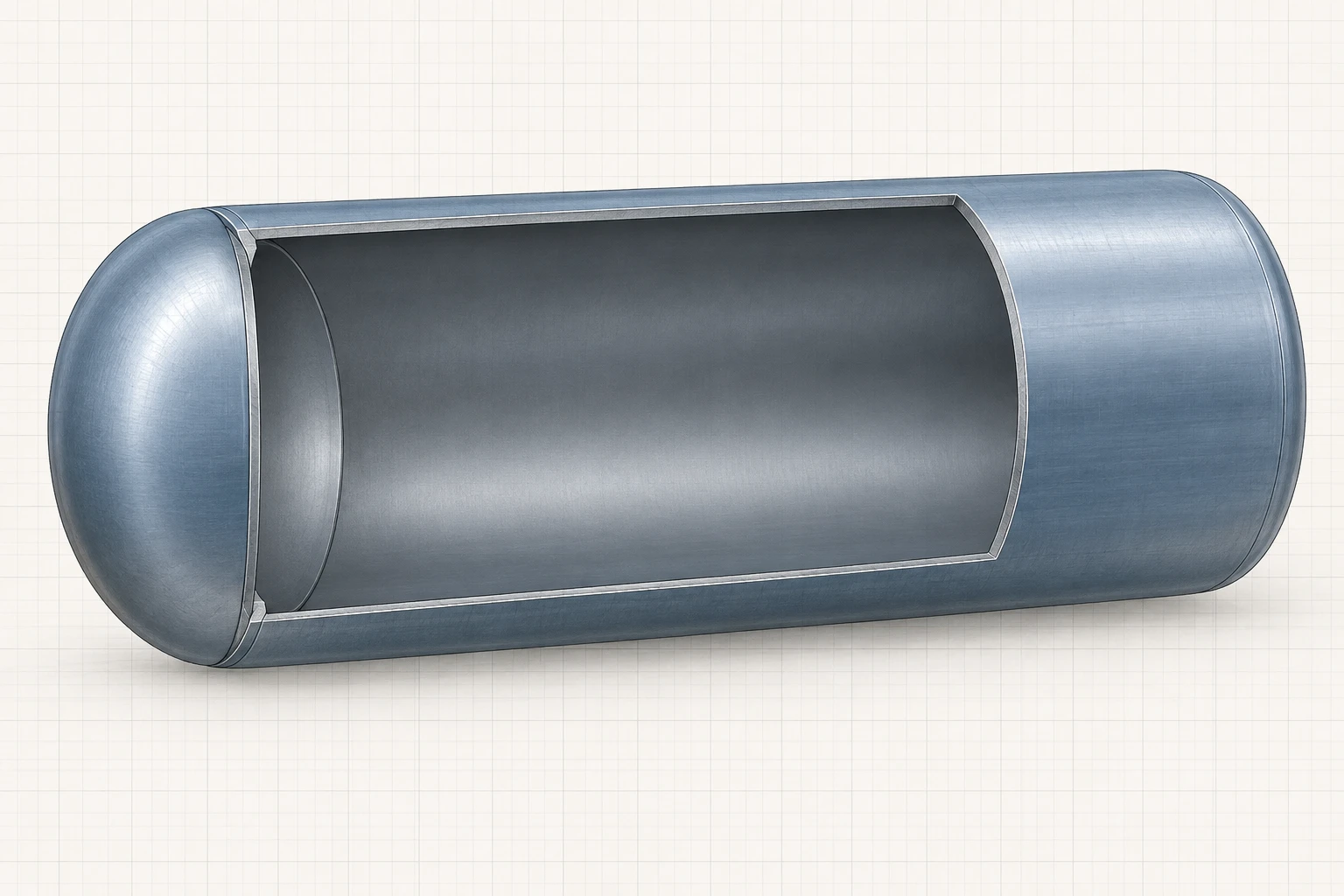
The cutaway makes the thin shell and closed-end geometry visible before the exact circumferential and longitudinal membrane-stress equations are applied.
Reading the Vessel Cutaway
Use the shell's circumferential direction and the closed end cap as the two physical free-body orientations behind the hoop- and longitudinal-stress formulas. The raster is a qualitative geometry aid: it supplies no pressure, dimension, stress value, or code threshold, so use the stated thin-wall check and the interactive model for exact interpretation.
Spherical Vessel Stress
Uniform tangential membrane stress in a thin spherical pressure vessel.
Why Spheres Are Efficient
A sphere carries internal pressure through equal membrane stress in every tangential direction. For the same diameter, wall thickness, and pressure, its membrane stress equals the cylinder's longitudinal stress and is half the cylinder's hoop stress.
Closed Spherical Vessel
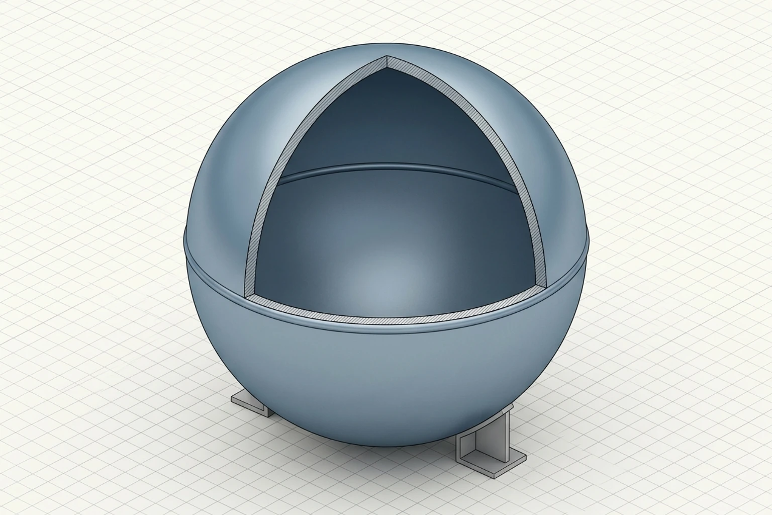
The cutaway makes the sphere's continuous closed-shell geometry visible beside the membrane-stress relation; it supplies no stress value or sizing detail.
Reading the Spherical Shell Geometry
Observe how the shell curves continuously around the vessel rather than changing into a cylindrical wall. The raster supports the geometric idea of equal tangential directions, but it supplies no membrane-stress value, thickness criterion, or design detail.
Interactive Exploration
Vary pressure, diameter, wall thickness, and vessel type. Confirm the linear effect of pressure and diameter, the inverse effect of thickness, and the two-to-one cylinder hoop-to-longitudinal stress ratio.
Controls
Within the lesson's t/r ≤ 0.1 criterion.
σh = pD/(2t)
σl = pD/(4t)
For the ideal closed thin cylinder.
Joint Efficiency
Joint efficiency represents the reduction in effective strength associated with a seam or joint relative to the base material.
Using Joint Efficiency
When a design method includes joint efficiency, apply it consistently to the allowable capacity or required thickness according to the adopted design model. Do not silently mix an efficiency-adjusted formula with a separate unadjusted allowable-stress assumption.
Continuous Shell Seam
The local section reveals a continuous longitudinal seam in the thin shell; joint efficiency remains an authored concept rather than a raster claim.
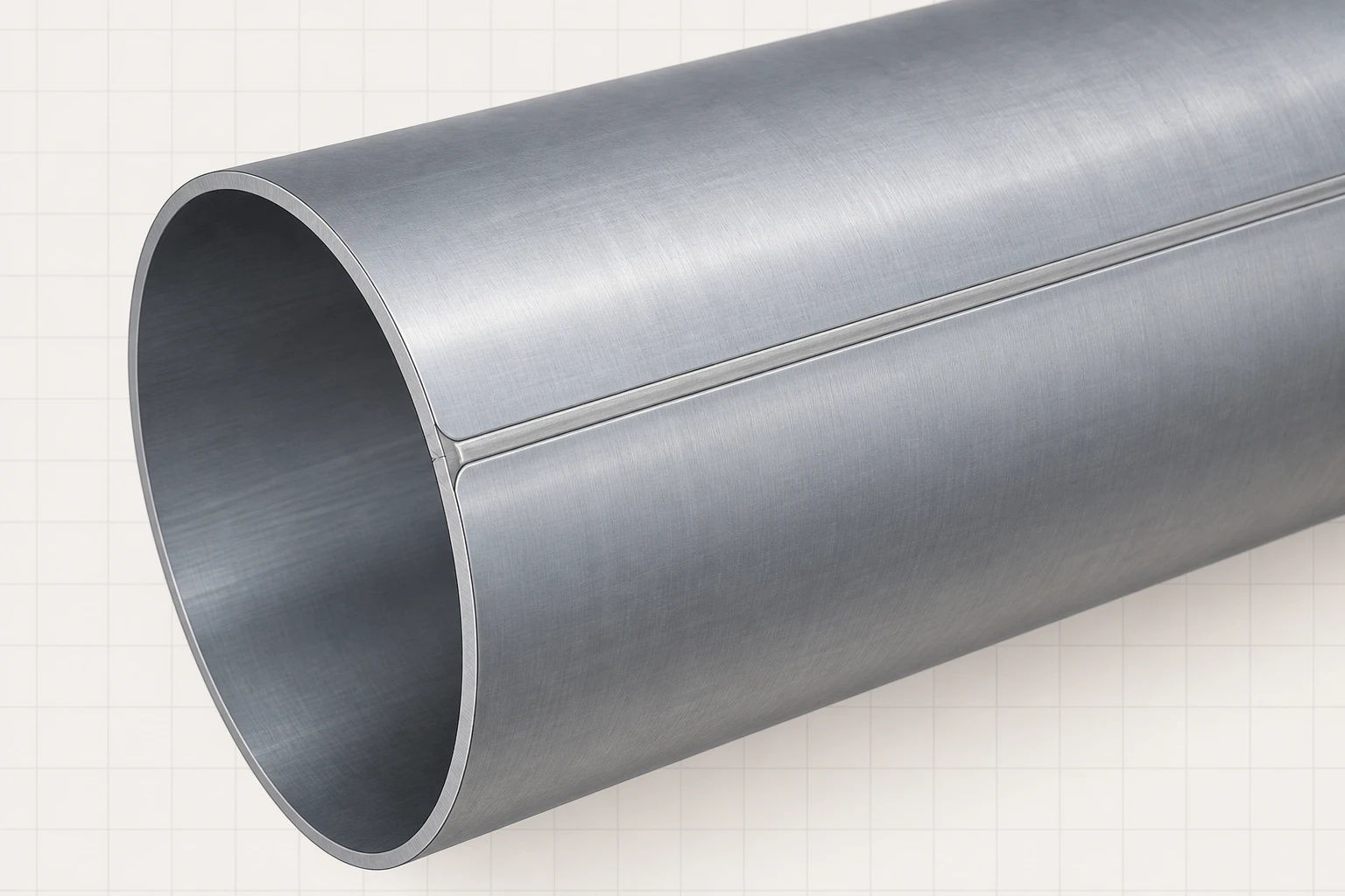
Reading the Seam Detail
Use the seam as a physical reminder that a shell is assembled from joined material surfaces. The raster shows qualitative joint continuity only; it gives no weld size, efficiency, leak condition, strength, or design conclusion.
- Verify thin-wall applicability before using membrane equations.
- Cylinder hoop stress is and is twice the longitudinal stress .
- A thin sphere carries uniform tangential membrane stress .
- Pressure and diameter increase membrane stress; greater wall thickness reduces it.
- Joint efficiency modifies capacity assumptions and must be stated explicitly.